We often judge a computer by its memory. This because a larger memory allows you run larger and more complex programs. But, what does memory actually mean? where is this data actually stored?


how does memory in a relay computer work?
The idea of memory is very straight forward. If an object, having multiple states/configurations, is put in one of its states and it stays in that state indefinitely it can be called a memory unit.
For example a tally counter:

You can set any 4 digit decimal number on a tally counter and that number stays as it is indefinitely unless it is reset or rewritten.
So a tally counter is a 4 digit memory and each digit has ten states and hence it can save any number from 0 to 9999.
By the same concept a latching Switch that we use daily to control home appliances is also a form of memory.

A simple latching switch is a single bit memory unit i.e. it saves a single binary digit having only two states ON and OFF. Since each switch denotes 1 binary digit, if you want to save a large number in this kind of memory you just need more of these latching switches.
The relay computer I am building is a digital machine that works in binary. Hence, we need to devise a re-writable memory unit that saves binary digits.
For doing so we could use relays as "Latches". This is how it could be constructed:
 By connecting the common pin to the input of the coil and connecting the 12V supply to NO contact we create a positive feedback loop.
when the relay coil isn't powered the relay stays OFF. once the coil is powered the common terminal gets connected to the NO contact. Since the common terminal is connected to the coil and NO is connected to 12V the coil is being powered by both the input as well as the 12V supply.
Thus, even if the input is removed the coil stays ON since it is still powered via the NO and common terminals. In this way the relay acts as a "Latch" and stays ON till there is 12V supply on the NO terminal. Shown below is the animated version of this latching behavior of the relay circuit:

The integrity of the data stored on the relay depends on the power supply. Once the 12V supply is removed the data is lost. Hence, it is a kind of volatile memory.
While we can set a relay to ON we still need a way to reset it or switch it OFF .This can be achieved by disconnecting the 12V source using another relay.
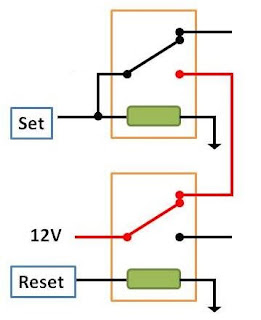 In the given diagram I have tried to show the circuit of the resetting mechanism. 12V supply is connected to the NO contact of the latching relay (top one) via the resetting relay (bottom).
when the resetting relay coil is not powered the above latching relay can be set to the On state. Switching ON the bottom resetting relay disconnects the 12V from the latching relay which in turn sets the latching relay in its OFF state.
Given below is an animation for demonstrating the resetting mechanism:

Taking 8 of these 1 bit memory circuits together gives us 1 byte of re-writable volatile memory. In the upcoming posts I will try and show you how this memory unit is actually used in the relay computer,
till then...

when the relay coil isn't powered the relay stays OFF. once the coil is powered the common terminal gets connected to the NO contact. Since the common terminal is connected to the coil and NO is connected to 12V the coil is being powered by both the input as well as the 12V supply.
Thus, even if the input is removed the coil stays ON since it is still powered via the NO and common terminals. In this way the relay acts as a "Latch" and stays ON till there is 12V supply on the NO terminal. Shown below is the animated version of this latching behavior of the relay circuit:

The integrity of the data stored on the relay depends on the power supply. Once the 12V supply is removed the data is lost. Hence, it is a kind of volatile memory.
While we can set a relay to ON we still need a way to reset it or switch it OFF .This can be achieved by disconnecting the 12V source using another relay.

when the resetting relay coil is not powered the above latching relay can be set to the On state. Switching ON the bottom resetting relay disconnects the 12V from the latching relay which in turn sets the latching relay in its OFF state.
Given below is an animation for demonstrating the resetting mechanism:

Taking 8 of these 1 bit memory circuits together gives us 1 byte of re-writable volatile memory. In the upcoming posts I will try and show you how this memory unit is actually used in the relay computer,
till then...
Got any queries???
E-Mail me at: shashwath.sundar@gmail.com
Comments
Post a Comment